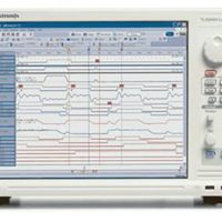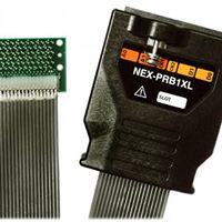
This is a logic probe. You connect this thing to a hardware resource on pc board. They have different probe for different applications. This thing reads the electrical signals going into and out of the hardware resource 'ie computer processor. These processors and other controllers have internal address and data lines as well as control and status lines. These lines are connected to internal registers that hold the 1's and 0's in those registers that relate to the address, data, control and status lines of the hardware resource (IC) chips and chip sets that belong to the paticular processor.
The only thing you'll need after that is the data book that goes with the IC. You'll need this for the instructions on how to initialize registers to make the darn thing work.